常問問題
- Check Fasteners: Inspect all bolts on the shot blasters and motors for tightness. Tighten any loose bolts immediately.
- Wear Parts Inspection: Examine the wear-resistant parts inside the shot blaster and the protective plates within the blast chamber. Replace any worn parts as needed.
- Blade Inspection: Inspect the blades and replace them when they are worn down to half their original thickness.
- Directional Sleeve Check: Verify that the directional sleeve pointer is correctly positioned.
- Blast Machine Doors: Ensure that all maintenance doors on the shot blasting machine are securely closed.
- Dust Removal System: Check for leaks in the dust removal pipes and inspect the filter bags for dust or damage. Replace damaged filters promptly.
- Separator Inspection: Check for debris or blockages on the separator’s spiral shell and filter screen. Clean as necessary.
- Flow Curtain Uniformity: Ensure the flow curtain in the separator is uniform and complete.
- Shot Control Valve: Verify that the shot control valve is closed.
- Switches and Indicators: Inspect all limit switches and proximity switches for proper operation. Ensure all signal lights on the control panel are functioning correctly.
- Motor Current: Check that the motor current for the shot blaster is within the rated range.
- Electrical Cabinet Cleaning: Clean the dust from the electrical control cabinet.
- Seals and Guards: Inspect the seals on the shot inlet pipe, work doors, and top seals. Replace if worn to prevent shot leakage.
- Debris Removal: Clear any debris from the bottom grid to ensure shot recycling.
- Shot Supply: Check the shot material level in the hopper. Refill if necessary.
Weekly Maintenance and Inspection
- Splitter Wheel: Replace the splitter wheel if worn down by more than 3mm.
- Directional Sleeve: Replace the directional sleeve if its opening has increased by more than 6mm.
- Protective Plates: Inspect the protective plates of the shot blaster for severe wear and misalignment.
- Dividers and Chutes: Check the wear on dividers and chutes and replace them if necessary.
- Recycling System: Inspect the fine powder and large particle tubes for recoverable shot material.
- Elevator Belt: Check the tension, bolts, and joints of the elevator belt. Adjust and replace as needed.
- Auger Inspection: Check for foreign objects and wear in the auger.
- Bottom Grid: Repair any leaks in the bottom grid.
- Pipe Joints: Inspect pipe joints to prevent leaks of air and dust.
- Dust Collector:Check the dust on the dust collector bag and use the pulse blowback mechanism in time.
- Compressor Maintenance: Drain water from the air compressor, storage tank, and oil-water separator.
Monthly Maintenance and Inspection
- Shot Control Valve Adjustment: Adjust the shot control valve to maintain the motor current between 12A and 14A.
- Drive Chain: Adjust and lubricate the drive chain.
- Elevator Belt Tension: Check and adjust the tension of the elevator belt. Tighten bucket bolts as needed.
- Gearbox Lubrication: Check the lubricant level in the gearbox and add the appropriate grease if necessary.
- Electrical Contacts: Check the contact status of each AC contactorand switches.
- Wiring Check: Tighten any loose wires in the power and control systems.
- Motor Test: Run individual motor tests to check for normal sound and current levels. Each motor should run for at least 5 分鐘.
- Fan and Duct Inspection: Inspect the wear and attachment of fans and ducts.
- Lubrication: Lubricate the bearings on the elevator, separator, and auger once a month with #2 calcium-based grease.
- Compressor Oil Change: Change the oil in the air compressor monthly.
Quarterly Maintenance and Inspection
- Bearing and Electrical Box: Inspect bearings and electrical boxes. Add new grease as needed.
- Wear Plate Inspection: Check the wear on the shot blaster’s wear plates.
- High-Speed Grease: Replace the high-speed grease in the shot blaster main shaft and motor bearings.
- Bolt and Flange Check: Inspect all bolts and flange connections on motors, gearboxes, fans, and augers for tightness.
Annual Maintenance and Inspection
- Complete Bearing Inspection: Inspect and lubricate all bearings, including motor bearings, with new grease.
- Chamber Repair: Replace or weld any worn protective plates in the main chamber.
- PLC and Inverter Check: Verify the contact reliability of the PLC and inverters.
- Ammeter Calibration: Ensure the ammeters are displaying accurate readings.
- Dust Collector Filters: Replace damaged filters and clean excessively dusty filters with an air gun.
- Duct Cleaning and Repair: Perform necessary cleaning and repairs on the duct system.
By adhering to these maintenance guidelines, you can ensure the efficient and safe operation of your ZMDE Shot Blasting Machine, thereby maximizing productivity and extending the machine’s lifespan. For further assistance, visit our support page.
H/T Steel Assembly,Welding and Straightening Machine Hydraulic Station Testing Instructions | |
|
Solenoid Valve Functions 1 — Electromagnetic Relief Valve (Main Pressure) 2 — Electromagnetic Directional Valve 3 — Pressure Reducing Valve 4 — Bi-Directional Throttle Valve A — Solenoid Valve Spool
Factory testing Results l Main Pressure: 8-10 MPa l 1-9 Channel Pressure: Adjusted to 7 MPa l 1-9 Channel Throttling: Open state l Speed: Adjusted to medium speed
|
Hydraulic Station Testing Steps
1.Power On: Turn on the power to start the motor.
2.Main Pressure Adjustment: Hold the No. 1 relief valve spool and watch the main pressure gauge, ensuring it reads 8-10 MPa. If not, adjust the relief valve handle clockwise to increase pressure or counterclockwise to decrease pressure.
3.Activate Directional Valves:
Sequentially turn on the 1-9 electromagnetic directional valves. Once energized, oil will flow to the AB port, filling the cylinder with oil and causing it to operate normally. Note that longer oil pipes may delay cylinder action.
4.Flow Control:
Rotate the No. 4 knob to control the flow and adjust the cylinder speed. Clockwise rotation slows down the cylinder, and counterclockwise rotation speeds it up. Alternate the top of the No. 2 solenoid valve spool back and forth before adjusting the throttle valve to ensure smooth operation.
5.Pressure Adjustment:
Factory settings have each circuit pressure at 7 MPa. If adjustments are needed, rotate the No. 3 knob clockwise to increase pressure or counterclockwise to decrease pressure. Pressure adjustments should be done with the cylinder fully extended or retracted to show accurate readings.
Hydraulic Station Diagnostics
- No Cylinder Movement:
Solution: Check if the cylinder is full of oil. Run the cylinder back and forth a few times to expel air and initiate movement.
- One-Way Cylinder Action:
Solution: Check if the solenoid valve spool is properly energized and creating normal suction. If it is, ensure the relief valve is also energized. Verify that the top of the spool is adequately positioned with a 2mm elasticity, indicating that the solenoid valve is not stuck. Inspect the throttle valve to ensure it is not restricted; it should be open before and after the throttle valve for normal operation. Observe the pressure regulation—pressure will be displayed when the cylinder is fully extended or retracted, but not in the middle position. Adjust the No. 3 knob as necessary: turn clockwise to increase the pressure or counterclockwise to decrease it.
- Motor Clamping Issues:
Solution: Check if the solenoid valve spool is properly energized and creating normal suction. If it is, ensure the relief valve is also energized. Verify that the top of the spool is adequately positioned with sufficient depth, indicating that the solenoid valve is not stuck. Inspect the throttle valve to ensure it is not restricted; it should be open before and after the valve for normal operation. Observe if the motor is showing pressure. If there is no pressure, adjust the No. 3 knob as necessary: turn clockwise to increase the pressure or counterclockwise to decrease it. The motor should reach a pressure of 7-8 MPa to operate. If the pressure shows 8 MPa but the throttle valve is not fully open, ensure that the No. 1 solenoid relief valve is energized. Alternate the energization of the solenoid directional valve left and right a few times to ensure proper operation. Once the hydraulic motor reaches the correct pressure and the solenoid valve is not stuck, the motor should operate normally.
- Cross-Channel Actions(activating one channel also causes action in another channel):
Solution: If activating one channel also causes action in another channel (indicative of a stuck valve), alternate the top position of the electromagnetic directional valve spool back and forth. Check if the spool reaches the correct depth and has a slight elasticity of about 1 mm when in place. If the spool can normally achieve suction, it indicates proper function. If impurities have entered the solenoid valve, it can cause the valve to stick and fail to create suction. This issue, known as valve sticking or coil damage, requires cleaning. Unscrew the four screws to remove the solenoid valve and clean it thoroughly. Ensure the spool moves freely back and forth within the valve body. If it feels stiff, use fine sandpaper to smooth it and then clean with compressed air before reassembling.
(5)Stuck Valve with Pressure Indication:
Solution: Manually move the spool or clean the solenoid valve to remove impurities. Ensure the spool moves freely.
By following these steps and solutions, you can ensure the proper testing and operation of the ZMDE 4KW/9-channel Hydraulic Station. Regular maintenance and adherence to these instructions will help maintain optimal performance and longevity of the equipment.
Welcome to the operational guide for the ZMDE Assembly, Welding, and Straightening Integrated Machine. This guide is designed to ensure you understand the proper usage and safety precautions for optimal performance in steel fabrication processes.
Operational Steps
1.Loading the Material:
- Place the material onto the feeding frame.
- Center the flange plate using the alignment mechanism.
- Clamp the web plate securely to prevent misalignment.
- Release the flange plate to avoid stress, and adjust the alignment cylinder to rise.
- Use a level or ruler to separatethe center line on the flange and web plates, with the web plate centered.
- Lower the alignment cylinder and begin feeding the material.
2.Feeding Process:
- During feeding, ensure the pressure cylinder is released to allow the material to pass smoothly.
- Keep the gun rack in the raised position.Adjust the current, 電壓, and welding speed based on the thickness of the material.
3.Straightening Adjustment:
- Once the plate passes through the straightening wheel, adjust the straightening wheel scale (the web width correction should not exceed 5cm).
- Return the plate to adjust the correction pressure and angle of the welding gun.
- Clamping and Welding:
- Securely clamp the flange and web plates.
- Adjust the torch angle and distance (2-3cm from the weld, with a 45° angle).
- Open the flux switch to cover the welding surface.
- Welding Process:
- Start the welding process and activate the flux recycling switch to reuse excess flux.
- Monitor and adjust the welding angle as needed during the process.
6.Straightening and Safety:
- After the plate passes through the straightening wheel, ensure personnel safety by avoiding the straightening wheel area.
- Adjust lifting mechanisms according to the shape and length of the plate.
Precautions for Operation
1.Preparation:
- Place the flange plate on a support frame that is level or slightly higher than the feed frame.
- Ensure the stability of the support and pre-mark the centerline for efficient centering.
2.Pre-Shift Checks:
- Inspect the drive system, lubrication, fastening parts, material cylinders, wire feeding system, arc conductive parts, and hydraulic system.
- Ensure all systems are filled, cleaned, and functioning without abnormalities.
3.Adjustments:
- Adjust current, 電壓, and travel speed based on the type of plate.
- Ensure all welding parameters meet the operational requirements and handle issues such as rust or oxidation beforehand.
4.Efficiency Calculations:
- Example: For an 8mm web and 10mm flange plate, with a travel speed of 700/min, welding a 10m piece should take about 15 分鐘.
- Calculate pre-preparation time and lifting operations to maximize hourly and daily output.Shorten the preparation time for loadingand lifting calculation 8min, 26m per hour processing components, 8h daily work calculation, daily outputsteel components 208m
5.Maintenance and Skill:
- Regular maintenance and skilled adjustment of welding parameters enhance efficiency and production capacity.
- Ensure daily maintenance is thorough and that operators are well-trained in adjusting the machine settings.
By following this guide, you can ensure the efficient and safe operation of the ZMDE Assembly, Welding, and Straightening Integrated Machine.
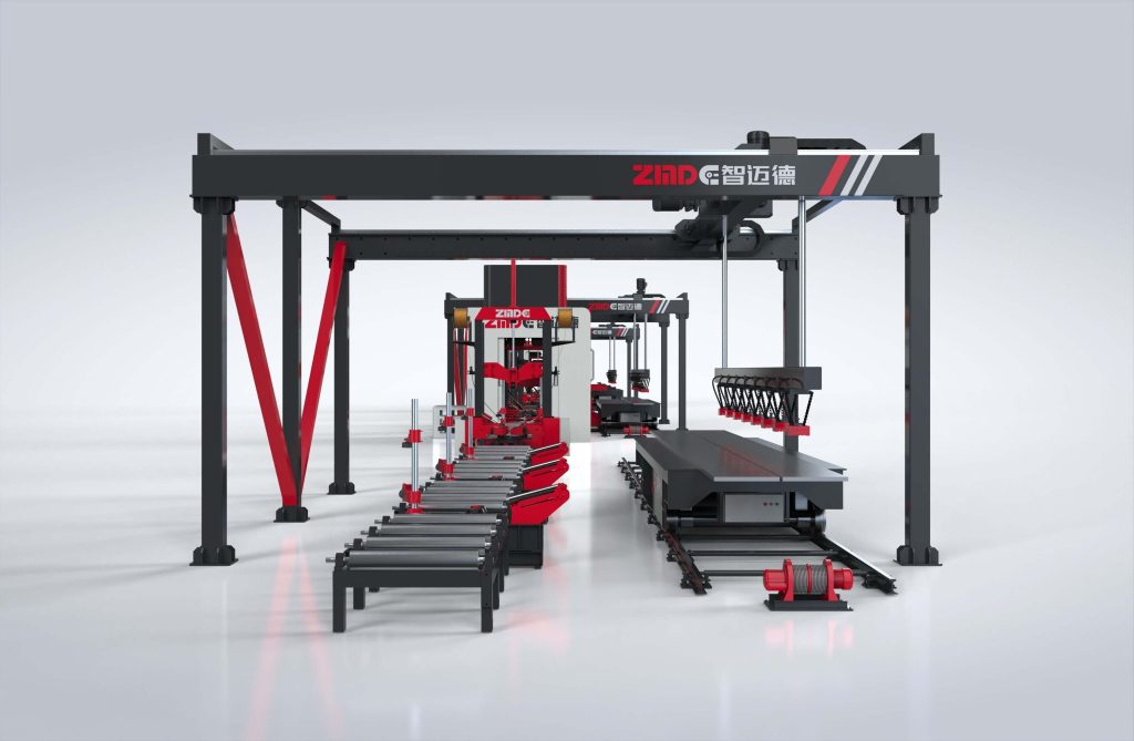
Equipment Name: U-Beam Assembly Machine
Overview
This machine is specialized equipment for assembling U-shaped and box-shaped beams. It mainly consists of a drive , frame, upper pressing device, side pressing device, hydraulic system, and electrical control system. The operation method is manual, using a stationary workpiece and a moving main machine for accurate positioning. The size of the applicable workpiece can be customized according to customer requirements.
Main Structure and Working Principle
- Main Structure:
It mainly consists of a drive, frame, upper pressing device, side pressing device, hydraulic system, and electrical control system.
- Drive : Symmetrically distributed, dual reduction motors drive wheels on the guide rail.
- Frame: The frame is made of square tubes, integrating horizontal and vertical guide rails as the support for the upper and side pressingdevices.
- Upper Pressing Device: Hooks hold the workpiece, two large topcylinders press, and two small cylinders push the carriage to move the top cylinders laterally for positioning.
- Side Pressing Device: The side pressing device uses one large top cylinder on each side of the workpiece to press, and one small cylinder to drag the carriage to position the side top cylinder vertically.
- Hydraulic System: The hydraulic system consists of an oil tank, filter cooling, pipelines, and various control valves, using No. 46 anti-wear hydraulic oil with a working pressure of 16MPa. Maintenance methods follow standard hydraulic station procedures.
- Electrical Control System: Uses PLC control to achieve various control functions.
- Working Principle:
This machine uses a stationary workpiece and a moving main machine to clamp the workpiece in sections, and the clamped workpiece is manually spot-welded into shape. The characteristics of this machine are a compact structure, low equipment and usage costs, good quality, and high efficiency.
Main Performance Parameters
– Applicable Workpiece Size (mm): 300mm-1200mm
– Suitable Workpiece Thickness (mm): ≤80mm
– Maximum Load Capacity (t): 20t
– Frame Travel Speed (m/min): 4m/min
– Hydraulic System Pressure (MPa): 16MPa
– Maximum Pressure of Left and Right Cylinders (t): 15t
– Maximum Pressure of Upper Cylinder (t): 30t
– Machine Power (kw): 10kw
– Maximum Stroke of Left and Right Cylinders (mm): 800mm
– Maximum Stroke of Upper Cylinder (mm): 1000mm
– Up and Down Travel of Left and Right Press Heads (mm): 1000mm
– Upper Cylinder Beam Extension Stroke (mm): 820mm
Operating Instructions
- The operator must be familiar with the structure and performance of the machine.
- First, turn on all power sources and check whether each part is normal.
- All cylinders must return to the initial position before working.
- During work, follow the company’s safety operation procedures to prevent accidents.
Equipment Maintenance
- Clean the main machine and roller parts after daily work, and lubricate each guide rail surface before starting the main machine.
- Lubricate the bearings and other transmission components of the conveyor roller with calcium-based grease every 15 working days; add N32 mechanical gear oil to the reducer and check once a month, replacing it every 6 months.
- Add 46#anti-wear hydraulic oil to the hydraulic station, check once a month, and replace it every 12 months.
Scope of Supply
- Main Machine Part: Main machine base, main drive system, left and right columns, bottom centering and pressing mechanism, lifting centering and pressing mechanism, upper platform, upper pressing mechanism.
- Electrical Control System: Main electrical control box, control system, operating system.
- Hydraulic System: Main hydraulic station, solenoid valve parts, pipeline system.
- Hydraulic pipeline seals, copper sliders, and other easily worn parts are not covered by the warranty.
Appendix: U-Beam Assembly Machine Safety Technical Operating Procedures
- Check for obstacles on the track before use.
- When working, first close the circuit breaker in the power distribution cabinet, then close the circuit breakers in the control cabinet in sequence.
- Turn on the oil pump, and its indicator light will be on.
- Lift the first base plate onto the material rack, and weld the inner partition according to the process requirements. Lift the left side plate close to the base plate and inner partition, adjust the upper and side cylinders to the appropriate positions according to the U-shaped beam size.
- Operate the left side pressing button to intermittently weld the side plate and base plate. Release the side cylinder, move the gantry a distance (distance according to process requirements), press the side cylinder again, and weld the side plate and base plate.
- Weld the right side plate in the same way.
- Lift the upper cover plate, press the upper and side cylinders, and weld the upper cover plate and side plates.
- After intermittent welding, release the upper and side cylinders, move the gantry, and proceed to the next welding section.
- After each shift, press the oil pump off button, turn off the control power, pull out the key switch, sequentially disconnect the circuit breakers in the control cabinet and the power distribution cabinet.
- Clean up the site after work, maintain the cleanliness of the machine, and carefully fill out the equipment maintenance records.
Table of Contents
- Purpose
- Main Technical Parameters
- Structure Principle, Adjustment, and Use
- Lubrication
- Foundation
- Installation
- Operation Procedures
- Maintenance, Safety, and Troubleshooting
- Purpose
This machine is a multifunctional shot blasting equipment used for steel structures and various welded parts. It can perform powerful shot blasting on the surface of steel in its original state, removing rust, welding slag, and oxide scales to achieve a certain level of cleanliness and a uniform metallic luster. This process relieves stress, improves the quality of the surface coating, and enhances the corrosion resistance of steel structures and materials.
The machine is suitable for stress relief and surface rust removal in metal structure welding, steel products, railway vehicles, construction machinery, shipbuilding industry, and bridge manufacturing industry.
- Main Technical Parameters
- Import Size
- Width: 1500mm
- Height: 2000mm
- Conveyor Roller
- Working Speed: 0.5~4m/min
- Power: 4kw×2
- Length: 12000mm per side
- Shot Blasting Assembly (Eight Units)
- Model: Q034
- Shot Speed: 65~70m/s
- Power: 8×11kw
- Elevator
- Capacity: 120T/h
- Power: 7.5kw
- Separator
- Capacity: 120T/h
- Separation Zone Wind Speed: 4~5m/s
- Screw Conveyor
- Capacity: 120T/h
- Longitudinal Screw Conveyor Power: 5.5kw
- Horizontal Screw Conveyor Power: 4kw
- Separation Screw Conveyor Power: 4kw
- Dust Removal System
(1) Dust Collector:
- Model: Pulse Cartridge Dust Collector
- Air Handling Capacity: 20000m3/h
- Dust Removal Efficiency: 99%
- Number of Filter Cartridges: 12 pieces × 2
(2)Centrifugal Fan:
- Model: 4-72-8c
- Wind Pressure: 2022Pa
- Power: 11kw × 2
- Blowing Fan Power: 11kw
- Total Machine Power: 150kw
- Structure Principle, Adjustment, and Use
The machine is a roller conveyor high-performance shot blasting cleaning equipment. During the cleaning process, a speed-adjustable motor drives the conveyor rollers to send the workpiece into the blasting chamber. The workpiece surfaces are subjected to intense blasting from eight shot blasters from different spatial directions. The oxide scales and contaminants on the surfaces are quickly removed, and the surface obtains a certain level of roughness and brightness. The machine eliminates workpiece stress through intense impact, preventing deformation.
During the cleaning process, the mixture of shot and dust falls into the screw conveyor at the bottom of the chamber, which is then collected and lifted to the separator. Clean shots fall into the separator hopper, ready for reuse by the shot blasters. The dust-laden air is filtered by the dust removal system, achieving a dust removal efficiency of 99%.
This equipment consists of the following functional parts: main and auxiliary cleaning chambers, shot blaster assembly, conveying system, shot fall pipes, elevator, separator, shot conveying system, dust removal system, and electrical control system.
- Cleaning Chambers
(1) Structure
The cleaning chambers are composed of a main and auxiliary chamber. These are large cavity structures, with the upper part box-shaped and the lower part conical. Cleaning operations are performed within this sealed cavity, consisting of front and back auxiliary chambers, the main chamber, rubber curtains, protective guards in the shot blasting chamber, and shot blasters.
A: The main chamber has eight shot blasters installed at the top, bottom, front, and back. The spatial arrangement has been tested and proven to achieve optimal cleaning of the workpieces.
B: The cleaning chamber is a multi-chamber assembly, with both the front and back being sealed. It includes multiple layers of rubber curtains to prevent shot leakage and maintains a slight negative pressure to prevent dust from escaping.
C: Wear-resistant guards are installed inside the main chamber to protect the chamber walls from wear, significantly extending the chamber’s lifespan and utilizing the reflection of shots to continue effectively impacting the surface of the workpieces, thereby enhancing cleaning quality and efficiency.
D: The protective guards inside the shot blasting chamber are covered with wear-resistant nuts and are bolted on, protecting the bolt heads from damage and facilitating easy disassembly and replacement.
(2) Adjustment, Use, and Safety
A: The protective guards and cast nuts inside the shot blasting chamber are susceptible to wear and should be regularly checked for wear and replaced promptly. Care should be taken when installing the guards to ensure overlapping, preventing damage to the chamber walls and ensuring safety.
B: The rubber curtains inside the cleaning chamber are prone to wear and should be repaired or replaced promptly if damaged, to prevent the escape of shots and dust.
C: During operation, personnel should stay away from the chamber entrances and exits to prevent shot splatter into the eyes, and warning signs should be hung.
D: When entering the cleaning chamber for maintenance, the power must be disconnected in advance, warning signs hung, and powered operations are strictly forbidden as they could endanger personal safety.
- Roller Conveyor and Conveying
(1)Structure
- The workpiece conveying system consists of a roller conveyor powered by a cycloidal pinwheel reducer, which has a strong load capacity.
(2)Adjustment and Use
- Adjust the speed of the conveying system from slow to high, gradually based on the cleaning effect on the workpieces, to achieve a high-quality cleaning effect and good economic performance.
- Shot Blasters
(1)Structure
- The shot blasters consist of an impeller, blades, a directional sleeve, and an inlet pipe. Shots are fed into the distributor wheel through the inlet pipe, pre-accelerated, and then ejected through the mouth of the directional sleeve, with the blades continuing to accelerate them to high speeds to forcefully impact the workpieces for cleaning.
Adjustment and Use:
- A: To adjust the shot projection zone, first close the shot gate, place the workpiece in the projection area, stop the roller conveyor, ensure safety, then open the shot blaster, manually introduce a small number of shots into the shot pipe, and after the shot blaster stops, pull out the workpiece to check if the striking position is appropriate. Adjust the directional sleeve up or down as needed.
- B: Uneven wear on the impeller can cause severe vibration in the high-speed running shot blaster. Check the condition of the blades before each shift and replace them if they show deep grooves or are worn more than half. Blades must be replaced in symmetrical pairs, and the weight difference between two blades should not exceed 5 grams.
- C: Check the ammeter readings on the shot blaster; they should indicate the appropriate shot flow.
- D: Do not open the shot blaster’s cover while it is still moving or while the power is not completely disconnected.
- Elevator
(1)Structure
The machine features a flat belt-driven bucket-type elevator, with the housing welded into shape, used to lift the mixture of shots and dust from the lower spiral conveyor to the top of the machine.
A: The elevator uses large pulleys to increase friction, with the lower wheel being cage-type to prevent sand, slipping, and misalignment, ensuring smooth and reliable belt operation and effectively extending the belt’s lifespan.
B: If the belt in the elevator slips during operation, adjust the tensioning device or check for overload.
- Separator
(1) Structure and Principle
The separator is a BE-type curtain structure. The shot-dust mixture is evenly fed into the separation area by the feed screw conveyor, forming a uniform curtain of shot-dust, which passes through a 4-5 m/s horizontal airflow for shot-dust separation. Shots and waste materials are separated based on their specific gravity, with clean shots falling into their respective channels; after passing through a grid, they enter a hopper for use by the shot blasters, while fine dust is drawn into the dust removal system, and the purified air is discharged into the atmosphere, capturing particulate dust.
(2)Adjustment and Use
A: Adjusting the gap of the separator’s tongue plate can control the uniform distribution of the shot-dust curtain, achieving optimal separation effects.
B: The separator’s outlet and the dust removal system’s pipe connection have an airflow adjustment gate, which must be adjusted to an appropriate position to ensure that usable shots are not lost to the waste bin.
C: Qualified shots passing through the separator’s screen effectively prevent larger objects from entering the hopper, ensuring the safe operation of the shot blaster.
- Spiral Conveyor
(1)Structure
A spiral conveyor and shot fall chute are located under the cleaning chamber to collect the mixture of shots and dust, which is then sent to the elevator and on to the separator. They consist of a cycloidal pinwheel reducer, spiral shaft, housing, and bearing seat.
(2)Adjustment and Use
A: After installation, the spiral conveyor shaft should rotate flexibly without any jamming.
B: Excessive shots in the spiral conveyor trough can increase the starting torque, leading to equipment failures. Issues should be promptly resolved, and large quantities of shots should not be added to the collection hopper at once but rather introduced slowly.
- Shot Conveying Pipes
The shot conveying pipes have a dual function, each gate tube is equipped with a gate plate for adjusting the flow of shots and facilitating maintenance. The opening and closing are controlled by an electromagnetic valve below.
- Dust Removal System
The dust removal system mainly consists of dust removal pipes, a pulse cartridge dust collector, fans, and air ducts. The dust removal efficiency of this system is 99%, achieving high dust removal performance. The air containing dust can be directly discharged into the atmosphere after dust removal, without the need for purification equipment. This complies with the “Comprehensive Standards for the Control of Air Pollution” (GB16297-1996) and the “Industrial Standards for the Emission of Waste” (GBJ14-93).
- Lubrication
New equipment needs to be lubricated according to the requirements before use.
No. | Lubrication Part | Lubrication Points | Lubrication Cycle | Lubricant Type |
1 | Shot Blaster Motor |
| Weekly | 2# Calcium-Based Grease |
2 | Pillow Block Bearing |
| Quarterly | 2# Calcium-Based Grease |
3 | Cycloid Pin Wheel Reducer |
| Semi-Annually | 30# Machine Oil |
4 | Chain |
| Semi-Annually | 30# Machine Oil |
5 | Cycloid Pin Wheel Reducer Motor |
| As per motor manual |
|
6 | High-Pressure Centrifugal Fan Motor |
|
|
|
- Foundation
The foundation diagram provided by our company only offers the installation position, embedded parts, and pit dimensions for user reference. Users must design the civil engineering based on local water level geological data and machine weight.
- Installation
The machine is divided into groups for transportation convenience. During on-site installation, reshaping should be done as per the situation.
- Operation Procedures
- Pre-Shift Equipment Check
- (1) Check the wear condition of the protective plate and door curtain of the shot blasting chamber. Report any issues and replace them promptly.
- (2) Ensure no one is inside or near the inlets and outlets before starting the machine.
- (3) Follow the electrical operation instructions during the process.
- Maintenance, Safety, and Troubleshooting
- Maintenance and Care
- The machine should be regularly inspected, maintained, and lubricated.
- Do not leave tools, screws, or other debris inside the machine during maintenance.
- Ensure the pit is dry to prevent rusting and clumping of the shot material. If the machine is unused for a long time, run it for half an hour periodically.
- Regularly remove waste from the separator and dust collector to ensure normal operation.
- Pre- and Post-Operation Checks
- Check the wear condition of protective plates, rubber curtains, and other vulnerable parts before operation, and replace them promptly.
- Check the fit of all moving parts and tighten any loose bolts promptly.
- Remove any debris inside the machine to prevent blockages, and check that all lubrication points meet the standards.
- Ensure no one is inside or near the inlets and outlets before starting the machine.
- Follow the electrical operation procedures correctly.
- Operation Checks
- Regularly check the cleaning quality of the workpieces during operation and adjust the shot blasting angle and conveyor speed as needed.
- Monitor the workpieces to ensure they are not misaligned and adjust them promptly.
- Pay attention to the vibrations and sounds of the shot blasters, as well as the temperature rise of bearings and motors. Stop the machine for inspection and replace the blades if any abnormalities are found.
- Safety
- Only qualified personnel are allowed to operate and maintain the machine.
- Disconnect the power supply and hang warning signs in visible locations during maintenance.
- Avoid open flames near rubber curtains and dust collectors.
- Ensure protective covers are securely installed during machine operation.
- Disconnect the main power supply in case of a power outage.